Applicable version(s):
Latest stable release & Development version
by Simone Manini, Orobix Srl, Italy
This tutorial demonstrates how to generate particles and streaklines from a velocity vector field and how to animate them.
Overview
Fluid flow is characterized by a velocity vector field in three-dimensional space, within the framework of continuum mechanics. Streamlines, streaklines, and pathlines are field lines resulting from this vector field description of the flow. They differ only when the flow changes with time: that is, when the flow is not steady. Streamlines are a family of curves that are instantaneously tangent to the velocity vector of the flow. These show the direction a fluid element will travel in at any point in time. Streaklines are the locus of points of all the fluid particles that have passed continuously through a particular spatial point in the past. Dye steadily injected into the fluid at a fixed point extends along a streakline. Pathlines are the trajectories that individual fluid particles follow. These can be thought of as “recording” the path of a fluid element in the flow over a certain period. The direction the path takes will be determined by the streamlines of the fluid at each moment in time. Timelines are the lines formed by a set of fluid particles that were marked at a previous instant in time, creating a line or a curve that is displaced in time as the particles move.

Figure 1: The red particle moves in a flowing fluid; its pathline is traced in red; the tip of the trail of blue ink released from the origin follows the particle, but unlike the static pathline (which records the earlier motion of the dot), ink released after the red dot departs continues to move up with the flow. (This is a streakline.) The dashed lines represent contours of the velocity field (streamlines), showing the motion of the whole field at the same time.
Requirements
In order to properly compute traces it is mandatory to have n mesh files resulting from a pulsatile cfd simulation. Each mesh file represent a timestep and must have, as a vtkDataArray, 3 velocity components in the axial directions ( usually u, v and w ), or the velocity vector.
Pre-process your solution
We need to create a mesh file which will contains all the data relative to the velocity components for each timestep we want to generate traces. We have to provide:
- the folder where the mesh solution files are located (-directory)
- the pattern of the mesh files name (-pattern)
- the first timestep and the last timestep we want to use (-firststep and -laststep)
- the step interval (-intervalstep)
- the output file name (-ofile)
In my example I used Gnuid for the cfd and my output files are in the following format:
gnuid_timestep.vtu
In which the timestep is represented with 6 numbers (e.g. gnuid_002225.vtu)
vmtkmeshmergetimesteps -directory ~/Desktop/particle_test -firststep 2225 -laststep 3600 -intervalstep 10 -pattern gnuid_%6s.vtu -ofile mesh_timesteps.vtu
If you have the velocity vector instead of velocity component arrays use -velocityvector 1 and -vector name as parameters of vmtkmeshmergetimesteps. Please specify the name of your vector. This feature is currently available only in Development version.
Then we need to have a source for generating traces and we can create it either with Paraview or vmtk.
In paraview you simply have to load one mesh file of your solution, apply a slice filter near your input boundary and save it as a polydata file. With vmtk you can do the same by using the vmtkmeshcutter script:
vmtkmeshcutter -ifile mesh.vtu -ofile source.vtp
If you need to clip the model before applying a slice:
vmtkmeshclipper -ifile mesh.vtu --pipe vmtkmeshcutter -ofile source.vtp
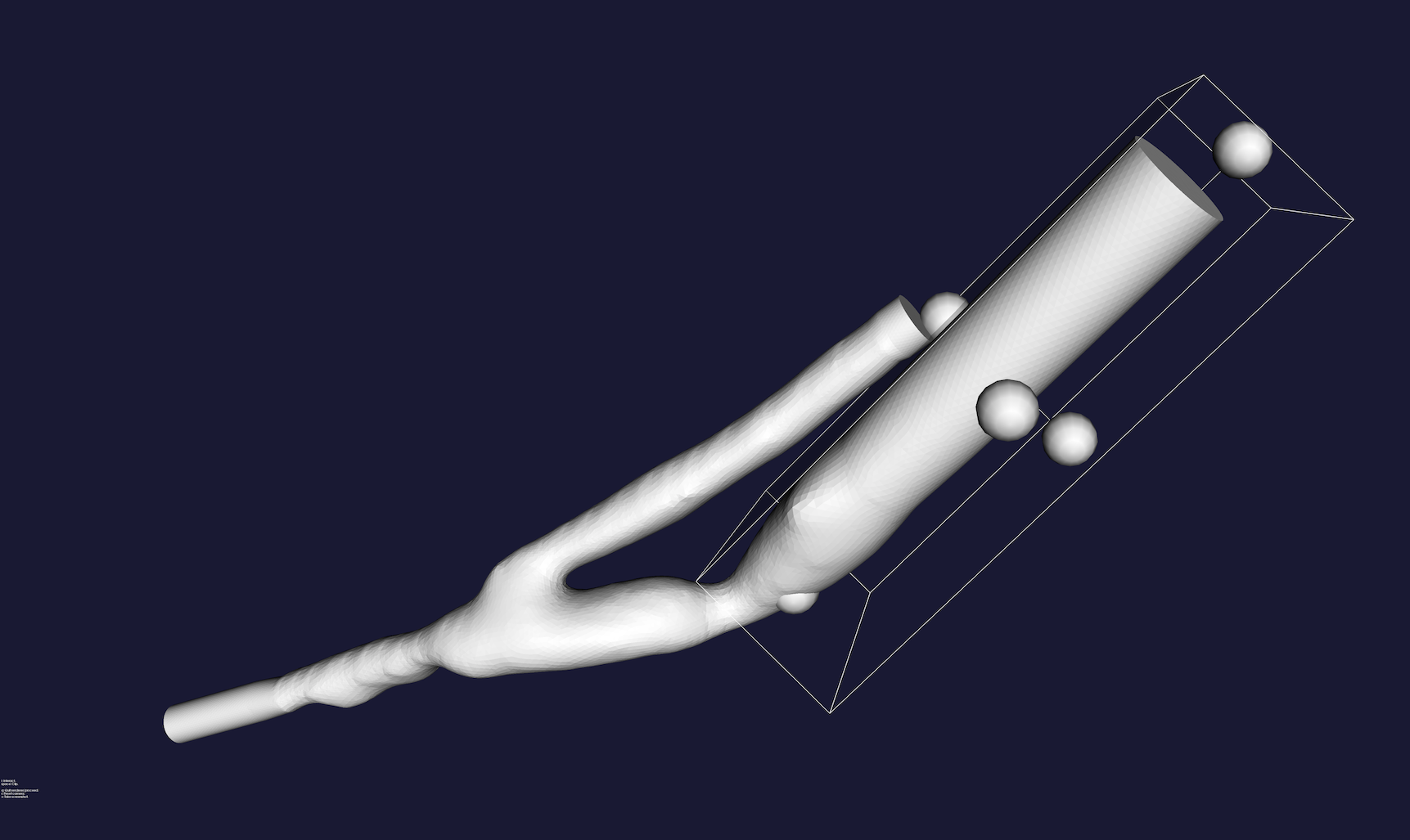 Figure 2: Clipping the mesh
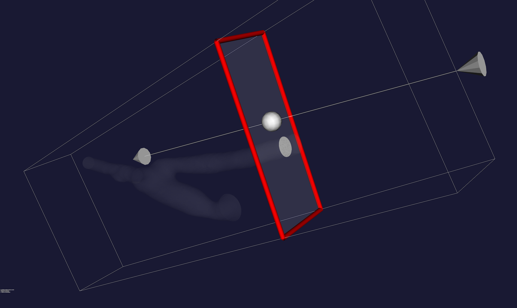 Figure 3: Creating a source slice for the particle tracer
Generate the traces
We will now see how to generate the traces from a velocity field. We have to provide to the script:
- the mesh file with all the timesteps (-ifile)
- the source polydata file (-sfile)
- the minimum velocity threshold in order to excude traces near the surface walls, by default is 5 cm/s (-minspeed)
- Optionally we can apply a linear subdivision filter in order to create 4 triangles for each triangle in the polydata. (-subdivide)
The output file will be a polydata file:
vmtkparticletracer -ifile mesh_timesteps.vtu -sfile source.vtp -ofile traces.vtp
Or we can build a pipe in order to avoid to write to disk the mesh_timesteps.vtu file and setting it as input for particletracer script.
vmtkmeshmergetimesteps -directory ~/Desktop/particle_test -firststep 2225 -laststep 3600 -intervalstep 10 -pattern gnuid_%6s.vtu --pipe vmtkparticletracer -sfile source.vtp -ofile traces.vtp
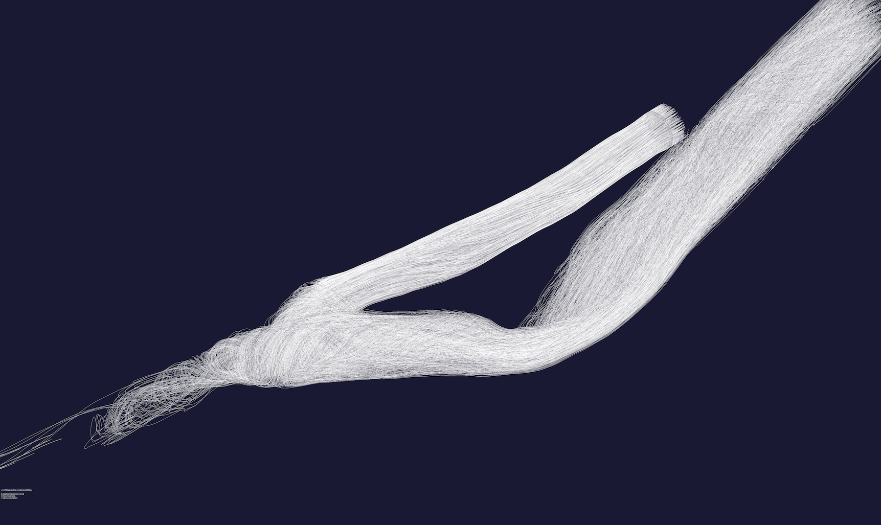
Figure 4: The traces generated with vmtkparticletracer script
Animate the traces
We are now ready to animate our traces. We have to provide to the script:
- the polydata file with the traces (-ifile)
- the timestep in order to set the velocity of the animation (-timestep)
Optional arguments:
- the method of the animation: particles or streaklines (-method), default=’particles’
- the lenght of the streaklines (-streaklinetimelength)
- toggle legend bar on/off (-legend)
- the data array name (-array), default=’Velocity’
- the maximum value of the array (-arraymax)
- the unit of measurements for the legend (-arrayunit)
- the size of the particles (-pointsize)
- the width of the streaklines (linewidth)
- toggle screenshot feature on/off (-screenshot)
- the directory in which the script will save screenshots (-imagesdirectory)
In this example we animate the traces with the default method (particles):
vmtkpathlineanimator -ifile traces.vtp -timestep 0.001 -legend 1
If we want to visualize the particle tracing inside our mesh we can render the mesh and the traces animation in the same render window
vmtkrenderer --pipe vmtkmeshviewer -ifile mesh.vtu -opacity 0.3 --pipe vmtkpathlineanimator -ifile traces.vtp -timestep 0.001 -legend 1
If we want to create a video we have to generate screenshots and then make a video with a dedicated software. I suggest quicktimepro (not free) or mencoder library (opensource).
vmtkrenderer --pipe vmtkmeshviewer -ifile mesh.vtu --pipe vmtkpathlineanimator -ifile traces.vtp -timestep 0.001 -method streaklines - legend 1 -screenshots 1 -imagesdirectory ~/Desktop/particle_images