Applicable version(s):
Latest stable release & Development version
*by Emilie Marchandise, Universite ́ catholique de Louvain, Institute of Mechanics, Materials and Civil Engineering (iMMC) *
This tutorial demonstrates how to mesh tubular geometries with Gmsh using the centerlines computed with vmtk. Gmsh is an open-source 3D finite element mesh generator. Starting from an STL file (that can be of very ol quality), the NEW ‘‘centerline field’’ of Gmsh enables you to automatically create a CFD mesh or FSI mesh for cardiovascular and respiratory flow simulations.
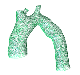
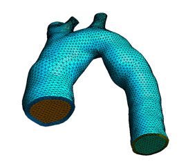
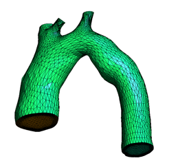
The procedure is able to generate different type of meshes, isotropic tetrahedral meshes, anisotropic tetrahedral meshes or mixed hexahedral/tetrahedral meshes. Additionally a multiply layered arterial wall can be generated with a variable thickness, function of th evessel radius. All the generated meshes rely on a mesh size field and a mesh metric that is based on centerline descriptions (distance to centerlines, local reference system based on the directions of the centerline and the normals to the centerline).
Before proceeding, make sure you went through the centerlines tutorial.
Using the tools
This tool is based on the centerlines of the tubular geometry that is computed with VMTK using the following command:
vmtkcenterlines -seedselector openprofiles -ifile tubeExtended.stl -ofile centerlines.vtp --pipe vmtksurfacewriter -ifile centerlines.vtp -ofile centerlines.vtk
It should be noted that prior to computing the centerlines, flow extensions can be added with vmtk for the inlet and outlets of the tubular geometry ,so that the computed centerlines extend out the inlet and outlets of the input tubular geometry
The NEW centerline filed of Gmsh takes as input the centerlines in vtk format. For the remeshing with gmsh, a Gmsh script file ( an ASCII text file with a .geo extension) has to be written.
The first lines of the file.geo file specify the 2D and 3D mesh algorithms as the input STL file:
 Mesh.Algorithm = 6; //(1=MeshAdapt, 5=Delaunay, 6=Frontal, 7=bamg, 8=delquad)
 Mesh.Algorithm3D = 1; //(1=tetgen, 4=netgen, 7=MMG3D, 9=R-tree)

 Merge "aorta.stl"
The next lines of the file.geo describe the Centerline Field:
 Field[1] = Centerline;
 Field[1].FileName = "centerlines.vtk";
 Field[1].nbPoints = 25; //number of mesh elements in a circle

 //Close in and outlets with planar faces
 Field[1].closeVolume =1;

 //Extrude in the outward direction a vessel wall
 Field[1].extrudeWall =1;
 Field[1].nbElemLayer = 4; //number of layers
 Field[1].hLayer = 0.2;// extrusion thickness given as percent of vessel radius

 //Remesh the initial stl
 Field[1].reMesh =1;

 Field[1].run;
 Background Field = 1;
As can be seen, three centerline-based operators can be defined: (1) a close-volume operator that creates and mesh the inlet and outlet faces of the tubular geometry, (2) a vessel wall model generation that extrudes the mesh in the outward direction, (3) a remeshing tool that creates a new surface mesh starting from the initial triangulation. If the close-volume operator is chosen, then a closed volume is created and Gmsh is able to create a volume mesh.
Use the command line ‘‘gmsh file.geo -3’’ to create the CFD or FSI mesh. The final mesh contains different physical tags: inlet, outlet, wall, lumenVolume (and also for FSI: outerWall, wallVolume, inletRing, outletRings).
Different examples on how to use this Gmsh’s Centerline Field can be found on the Gmsh wiki - use ‘gmsh’ as username and passwd. Questions or suggestions can be send by email to : emilie.marchandise@uclouvain.be