Applicable version(s):
Latest stable release & Development version
This tutorial demonstrates how to process a surface model (obtained like in this tutorial or with other techniques) to generate a computational mesh for use in CFD.
We start off by assuming you have a 3D surface model of a vascular segment with blobby closed ends, like the ones generated using level sets or Lagrangian deformable models. If you already have a model with open inlets and outlets, just skip the Opening the surface section.
Smoothing the surface
Image segmentation can result in bumpy surfaces, especially if the image quality is not high and one didn’t use any curvature term in level sets evolution. Since artifactual bumps in the surface can result in spurious flow features and affect wall shear stress distributions, one may want to increase surface smoothness prior to building the mesh.
vmtksurfacesmoothing is a wrapper around vtkWindowedSincPolyDataFilter, which implements one of the non-shrinking filters by Taubin.
By typing:
vmtksurfacesmoothing --help
we see that there are two main parameters controlling the amount of smoothing: passband, which is the cut-off spatial frequency of the low pass filter, and iterations, which is the number of smoothing passes. For more details, visit the vtkWindowedSincPolyDataFilter doxygen page.
For typical vessels, the following should be ok
vmtksurfacesmoothing -ifile foo.vtp -passband 0.1 -iterations 30 -ofile foo_sm.vtp
If you want more smoothing, try using a passband of 0.01. Be careful not to kill surface features by smoothing too much. Also, watch out the apex of bifurcations, since its curvature may decrease resulting in a shallower apex and affecting the simulated hemodynamics.
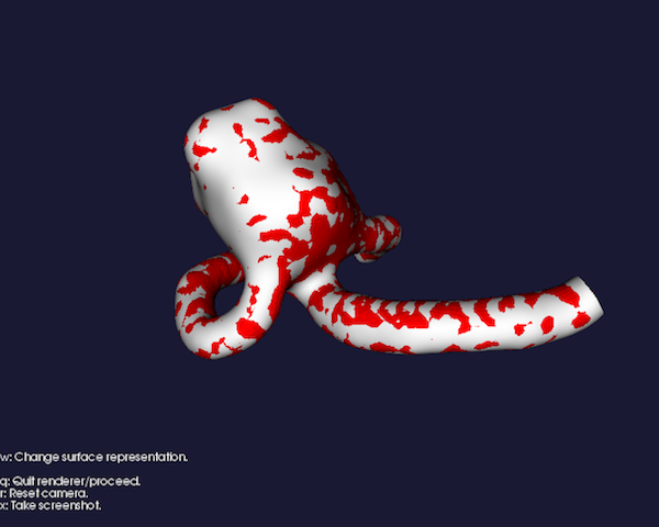
If you want to compare the smoothed and original versions, to make sure that no shrinking occured and the main surface features were preserved, try this
vmtksurfacereader -ifile foo.vtp --pipe vmtksurfacesmoothing -iterations 30 -passband 0.1 --pipe vmtkrenderer --pipe vmtksurfaceviewer -display 0 --pipe vmtksurfaceviewer -i @vmtksurfacereader.o -color 1 0 0 -display 1
You’ll see the original surface in red and the smoothed surface in gray.
A potential side effect of the filter is that it slightly shifts the position of the surface in space. If this occurs, try increasing iterations

Figure 1: Compare original surface with the smoothed one
Opening the surface
Under the assumption that you generated the surface using a deformable model, it’s likely that your surface is closed at inlets and outlets, with a blobby appearance. We’ll now proceed by opening the surface by clipping the blobby endcaps.
You have at least three options.
The first option is to use vmtksurfaceclipper. If you call
vmtksurfaceclipper -ifile foo.vtp -ofile foo_cl.vtp
a rendering window will show up.

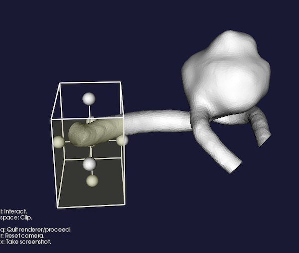
Figure 2: Surface clipper interaction
Press i to start the interaction. A cube will appear (like in vmtkimagevoiselector). Position the cube in such a way that the portion of the surface you want to clip lies inside the cube (it would be easier with a cyberglove, uh?). Try to position one face of the cube perpendicular to the vessel. You don’t need to be extremely precise, just do the best you can. It’ll get easier with time.
Press the space bar to proceed with clipping.
Press i again if you want to clip another piece, or q if you want to quit.
The third option is to clip endcaps automatically. No 3D interaction involved. Endcap clipping can be performed using vmtkendpointextractor, which needs centerlines to be computed beforehand with vmtkcenterlines. Let’s set up the corresponding pype
vmtksurfacereader -ifile foo.vtp --pipe vmtkcenterlines --pipe vmtkendpointextractor --pipe vmtkbranchclipper --pipe vmtksurfaceconnectivity -cleanoutput 1 --pipe vmtksurfacewriter -ofile foo_ct.vtp
When prompted, select one source point on one inlet or outlet and press q. Then select as many target points as the rest of inlets/outlets and press q.
If you look at the output file, you’ll see that the endcaps have been removed. If you want to clip a larger extent of the endcaps, just use the vmtkendpointextractor option numberofendpointspheres (the default is 2, increase it to 3 or 4 and see what happens).
Increasing the number of surface triangles (optional)
Sometimes, with low-resolution images, small vessels or stenoses, the number of triangles defining the surface can be low. This can cause potential problems to some mesh generation algorithms. The solution to this is to subdivide the mesh using a smooth subdivision scheme like Butterfly (the original points are preserved and new ones are added in such a way that at the limit it would produce a C1-continuous surface) or Loop (the original points are displaced but the limit surface is C2 continuous).
If you need to subdivide your surface, do the following
vmtksurfacesubdivision -ifile foo.vtp -ofile foo_sb.vtp -method butterfly
Adding flow extensions
Flow extensions are cylindrical extensions added to the inlets and outlets of a model. They are important for ensuring that the flow entering and leaving the computational domain is fully developed, so that fully developed boundary conditions aren’t forcing the solution in the actual vessel.
Adding flow extensions is a typical problem in CFD modeling. Stitching cylindrical flow extension to an inlet or outlet of a realistic vessel is not a trivial task, and may result in worsening the reproducibility and adding operator-dependence to the modeling procedure. A fully automatic procedure can solve this often overlooked problem preserving reproducibility and speeding up the modeling phase considerably.
Once again, adding flow extensions relies on centerlines. This time centerlines can use open inlet and outlet profiles for the definition of seed and targets.
Let’s see how this is done
vmtksurfacereader -ifile foo.vtp --pipe vmtkcenterlines -seedselector openprofiles --pipe vmtkflowextensions -adaptivelength 1 -extensionratio 20 -normalestimationratio 1 -interactive 0 --pipe vmtksurfacewriter -ofile foo_ex.vtp
The adaptivelength argument of the vmtkflowextensions script is a boolean flag which enables computing the length of each flowextension proportional to the mean profile radius. The proportionality factor is set through extensionratio. The normalestimationratio argument controls how far into the centerline the algorithm looks for computing the orientation of the flow extension.
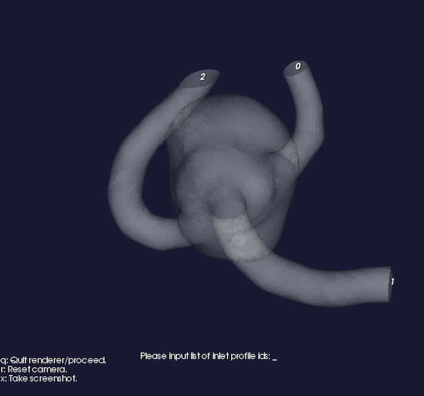
In the previous line, the flag -interactive 0 was specified. This means that vmtkflowextensions will not prompt the user about what inlet or outlet to extend, but it will perform the task on all the available open boundaries. The default behavior is -interactive 1, which prompts the user about which boundaries to extend through a graphical window. Once the rendering has started and you have determined what extensions to generate, press q and you’ll be asked to list the ids of the desired boundaries. Remember that you can pipe more than one vmtkflowextensions script one after the other if you need to perform the task repeatedly.

Figure 3: Adding flow extensions


