Applicable version(s):
Latest stable release & Development version
This tutorial demonstrates how to split a vascular segment into its constituent branches.
Before proceeding, make sure you went through the centerlines tutorial.
The theory behind this tutorial can be found in the following publication:
- Antiga L, Steinman DA. Robust and objective decomposition and mapping of bifurcating vessels. IEEE Transactions on Medical Imaging, 23(6), June 2004.
Overview
From now on we’ll make the assumption that our vascular segment has a tree-like topology, i.e. one inlet and several outlets, without any loops. This for the moment is quite a strong assumption, which in general holds true for arterial segments, not so much for venous segments; lifting the assumption will require some coding in the future. For the moment, if you’re left with a non tree-like network, you can always brake loops manually before proceeding.
After computing centerlines of a branching vascular segment we’re left with a bunch of lines each running from one inlet to one outlet. Although the geometry of the vascular tree is well represented by the set of centerlines, its topology, i.e. the way the single branches are interconnected, is not represented in any way.
vmtk recovers the topology of the vascular network from geometric information, namely centerlines and their associated maximum inscribed sphere radius. Please recall that each centerline point is associated to the radius of the maximum inscribed sphere defined in that point: this means that we can construct a tube around each centerline made from the envelope of maximum inscribed spheres. In general, each two centerlines in a vascular tree will mutually intersect the surface of the other centerline’s tube. We define this as a bifurcation. This is as usual easier to see than to read.
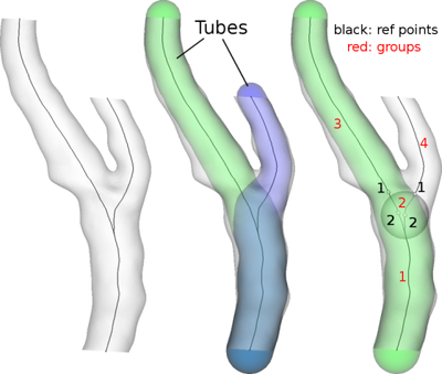
For each bifurcation, but this is generalized to a n-furcation, we identify two points on each centerline (which we termed the reference points): the first is located where the centerline intersects another centerline’s tube (in the vascular tree assumption, each centerline will intersect all the other centerlines’ tube once); the second is located one maximum inscribed sphere upstream, as the black numbers in the figure above. The second reference point may be seen as the start of the bifurcation region, although this intuitive explanation may depend on the geometry of the vessel.
So, at this point we can basically identify three tracts along each centerline, the first preceding the bifurcation, the second lying inbetween the two points and the last following the bifurcation. Note that in the first tract the two centerlines are one in each other’s tube. The same thing holds true for the second tract, since by definition the second tract ends where the centerlines exit the other centerline’s tube. The last tracts are instead outside each other’s tube.
We can therefore group the tracts based on these tube containment relationships: the first group will be composed of the first tracts of the two centerlines, the second of the second tracts of the two centerlines, the ones located at the bifurcation region inbetween the reference points, the third of the second tract of the first centerline and the fourth of the second tract of the second centerline. As shown in red numbers in the figure above. Each group will basically represent a branch, except for the second group, which will be relative to the bifurcation.
Splitting and grouping centerlines has a value that goes beyond centerline topology itself. Based on the splitting operated on the centerlines we can in fact split the surface into the branches corresponding to centerline groups. To understand how this is performed we again recall that each centerline is associated with maximum inscribed sphere radii, and that a sphere is a function with support in 3D and values negative inside and positive outside its surface. Therefore, the tube resulting from the envelope of maximum inscribed spheres is a function with support in 3D and values negative inside and positive outside the tube surface.
Having noted this, we can therefore compute the value of the tube function relative to one centerline on each point of the vessel surface: these will always be non-negative (since tubes are made of maximum inscribed spheres). We can also compute the value of a group of tube functions (relative to a group of centerlines) by taking the minimum value obtained across all tubes in the group. Thanks to these operations, we’re now ready to detach the surface of a branch from the rest of the bifurcation: we can do so by taking the difference between the values of the group of tubes relative to the branch minus the values relative to the ensamble of the rest of the tracts that are not relative to the bifurcation region, at each surface point. This will generate a scalar field on the surface which is negative on he branch under examination and positive elsewhere. For people used to Voronoi diagrams, this operation identifies the region of space closer (in the tube metric) to the branch group of centerline tracts than to all the other tracts. At this point the surface is split at the zero-level of the generated scalar field and the branch is detached. In order to split a bifurcating segment into its branches, this operation has to be repeated for each branch, by considering in turn all the centerline tract groups (except the one at the bifurcation).
Note that the bifurcation tract group is never taken into account for splitting the surface. For this reason we say that the bifurcation group is a blanked group.
Using the tools
The operations described above are implemented in two separate scripts, vmtkbranchextractor, which performs splitting and grouping on the centerlines, and vmtkbranchclipper, which takes care of splitting the surface given split and grouped centerlines.
Let’s perform the first step: let’s compute centerlines and split them
vmtkcenterlines -ifile foo.vtp --pipe vmtkbranchextractor -ofile foo_clsp.vtp
Of course foo.vtp must correspond to a bifurcating geometry.
After the scripts have run, foo_clsp.vtp will contain a set of lines, each representing one of the tracts into which all centerlines have been split. Let’s see how we can understand which tract is what in the output: we said that each centerline is first split into tracts, and that these tracts are grouped into branches. Having recalled this, each tract (i.e. each cell in the output) will be associated with three scalar fields:
CenterlineId, the cellId of the centerline the tract has been split fromTractId, the id identifying each tract along one centerlineGropuId, the id of the group the tract has been put into
Additionally, each tract also carries the information whether it belongs or not to a bifurcation group through the Blanking scalar field, which is 1 if the tract is in a bifurcation group and 0 otherwise. All the scalar fields are stored as CellData arrays in the vtkPolyData data structure representing the centerline tracts. Together, these scalar fields univoquely identify a tract in a network and its topological relationships with the other tracts.
Since, once again, this stuff is easier to see than to explain, it is possible to visualize the values of the scalar fields this way
 vmtkcenterlines -ifile foo.vtp --pipe vmtkbranchextractor -ofile foo_clsp.vtp
 --pipe vmtkcenterlineviewer -cellarray CenterlineIds
 --pipe vmtkcenterlineviewer -cellarray TractIds
 --pipe vmtkcenterlineviewer -cellarray GroupIds
 --pipe vmtkcenterlineviewer -cellarray Blanking
Just a note: if you decide to precompute centerlines, store them in a file and to use them or splitting later on, you have to tell vmtkbranchextractor what’s the name of the array containing maximum inscribed sphere radius values, this way
 vmtkcenterlines -ifile foo.vtp -ofile foo_cl.vtp
 vmtkbranchextractor -ifile foo_cl.vtp -ofile foo_clsp.vtp -radiusarray MaximumInscribedSphereRadius
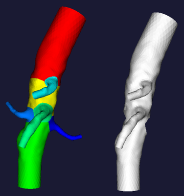
Let’s now move on to surface splitting. We now want to clip the surface in foo.vtp into its branches. We do it this way
vmtksurfacereader -ifile foo.vtp --pipe vmtkcenterlines --pipe vmtkbranchextractor --pipe vmtkbranchclipper -ofile foo_sp.vtp
You can visualize the results
vmtksurfaceviewer -ifile foo_sp.vtp -array GroupIds
(or you can pipe the latter, without the -ifile foo_sp.vtp, at the end of the previous command line)
You can also choose which branches to clip, by specifying a list of GroupIds of the branches you want in output
vmtksurfacereader -ifile foo.vtp --pipe vmtkcenterlines --pipe vmtkbranchextractor --pipe vmtkbranchclipper -groupids 0 -ofile foo_sp.vtp
All the other groups but 0 will be discarded.
The same feature is handy if you want to perform the complementary operation, i.e. to remove a branch. This is done by specifying the -insideout 1 option
vmtksurfacereader -ifile foo.vtp --pipe vmtkcenterlines --pipe vmtkbranchextractor --pipe vmtkbranchclipper -groupids 0 -insideout 1 -ofile foo_sp.vtp
Last, you can achieve the maximum splitting freedom by using vmtkcenterlinelabeler, with which you can interactively change the group ids of a split centerline
vmtksurfacereader -ifile foo.vtp --pipe vmtkcenterlines --pipe vmtkbranchextractor --pipe vmtkcenterlinelabeler -labelids GroupIds --pipe vmtkbranchclipper -groupids 0 -ofile foo_sp.vtp
The best way to learn this is to play with it and see what happens.
One recommendation: when clipping the surface of a vascular network, it is strongly advised that all branches have a centerline in their interior (for weird geometries, e.g. when you’re dealing with an aneurysm, you can always generate a centerline that enters the aneurysm). If this is not satisfied, spourious cuts may appear in the branches that do not contain a centerline.
One last observation: vmtkbranchextractor is not the only script dealing with splitting and grouping sets of centerlines. Also vmtkendpointextractor, described in the Prepare a surface for mesh generation tutorial, works the same way. Try running the script and visualize the results with vmtkcenterlineviewer to understand what it’s all about.