Applicable version(s):
Latest stable release & Development version
In this protocol it is explained how you can mask the bone with a sigmoid function to create a good mesh from for example the internal carotid artery or an aneurysm located near bone. The sigmoid function masks the high gradients in bone and air in order to decrease their influence on the levelset. If you can’t understand the used code, I advise you to look at one of the other tutorials on the vmtk website.
vmtk scripts
Basic PypeS tutorial
Image-based Modeling
Computing centerlines
From 3D surfaces to CFD meshes
Read and Display the image
The first step is to read in the dicom files and to display them on the screen. This is done using vmtkimagereader and vmtkimageviewer
vmtkimagereader -f dicom -d dicom_directory_path -ofile image_volume.vti --pipe vmtkimageviewer
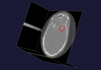
The next step is to select a volume of interest. If you look at the object using vmtkimageviewer you will see that the aneurysm is located on the Right Middle Cerebral Artery. Because I also wanted to test some code to reduce the influence of bone and air on the segmentation, I will also include the right Internal Carotid Artery in the volume of interest. When you are only interested in the aneurysm, it is best to create a volume of interest that only includes the aneurysm because of computational time needed for bigger volumes.
vmtkimagevoiselector -ifile image_volume.vti -ofile image_volume_voi.vti
 |
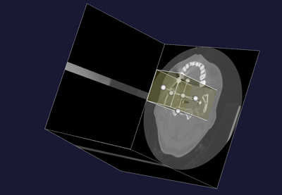 |
| Figure 1: location of the aneurysm | Figure 2: Volume of Interest selection |
Creating the sigmoid mask
To create the proper mask on the image it is necessary to locate regions of bone and air. Air was included later because it also has a steep gradient, but the values in the air level set are opposite to those of bone. It has the same effect as bone on the segmentation of a vessel. To properly locate these regions, vmtklevelsetsegmentation is used.
Bone and air segmentation
An isosurface of bone and air have to be made seperately. The values from bone and vessels can overlap, but still it is pretty important to choose an isosurface with a value that is as low as possible. (I did this in steps of 100) For this image I chose level 500 HU (Hounsfield Units) for the isosurface. Before you make the actual isosurface with vmtklevelsetsegmentation, you could make a surface with vmtkmarchingcubes in the following way:
vmtkmarchingcubes -ifile image_volume_voi.vti -l 500.0 --pipe vmtksurfaceviewer
This will give you an idea of what will be included in the isosurface. If you can recognize vascular structures, then you will have to increase the value of the isosurface in order to exclude the vascular structures from the levelset
The actual construction of the levelset of bone:
vmtklevelsetsegmentation -ifile image_volume_voi.vti -ofeatureimagefile bone_feature_500.vti -ofile bone_lvlset_500.vti
I used 500 iterations in vmtklevelsetsegmentation and kept the propagation, curvature and advection scaling at default values (0.0, 0.0, 1.0)
For air, the same thing can be done. The value for the isosurface I used was -50 HU.
vmtklevelsetsegmentation -ifile image_volume_voi.vti -ofeatureimagefile air_feature_-50.vti -ofile air_lvlset_-50.vti
If you then use vmtkimageviewer on the levelsetfiles you see that there is a difference between both. In order to add the levelsets together, all the values in the air levelset are multiplied with -1. (You could do the same with bone, but the sigmoid function was designed on the original bone levelset, therefore air will be negated). This can be done by setting the option negatei2 in vmtkimagecompose to 1. Mind that you have to put the air levelset at i2. With vmtkimagecompose you will also combine the two separate levelsets.
vmtkimagecompose -ifile bone_lvlset_500.vti -i2file air_lvlset_-50.vti -negatei2 1 -ofile bone_air_lvlset.vti
How to segment specific regions
When creating the levelsets of bone and air, it is wise to choose a relatively small volume of interest, because it may take a while before the process is completed. With VMTK it is also possible to make a smaller volume of interest in the one you already made, which contains the region of bone that you want to segment (I.e. the region where the aneurysm/vessel is very close to the bone)
 |
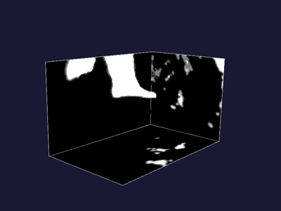 |
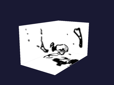
| Figure 3: Bone levelset | Figure 4: Air levelset |
 |
|
| Figure 5: Bone and Air levelsets combined |
vmtkimagevoiselector -ifile image_volume_voi.vti -ofile image_volume_voi_2.vti
With this volume of interest, you can segment bone and air in the same way as mentioned previously. However, because you made a smaller volume of interest, you can not add the segmentations together and use the original volume of interest to do the segmentation of your vessel. The following steps have to be taken to be able to segment the vessel.
After the segmentation of a piece of bone you were interested in, the levelset image has to be resliced with vmtkimagereslice. This script will paste your levelset in the original volume of interest in the correct position
vmtkimagereslice -ifile piece_of_bone_voi_2.vti -rfile image_volume_voi.vti -background10.0 -ofile piece_of_bone_voi.vti
The option -background will give the values outside the smaller volume of interest the value 10.0. This is important when you will use vmtkimagecompose to combine the smaller pieces of bone in a big piece of bone. If you do not add the -background option, the final levelsets file will miss some information due to the operation vmtkimagecompose uses to compose the images.
Adding the smaller pieces together:
vmtkimagecompose -ifile piece_of_bone_voi.vti -i2file another_bone_piece.vti -ofile big_piece_of_bone.vti
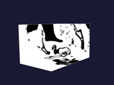
Correct the feature image
In this composed image the positions of the gradients you want to mask can be seen in black. vmtkimagefeaturecorrection masks the feature image with a sigmoid function. The feature image that will be masked is either the feature image from the bone segmentation or the feature image from the air segmentation (they are the same, so it makes no difference). There are three options that can be set to adjust the sigmoid function. (sigma, scalevalue, computescalevaluefrominput)
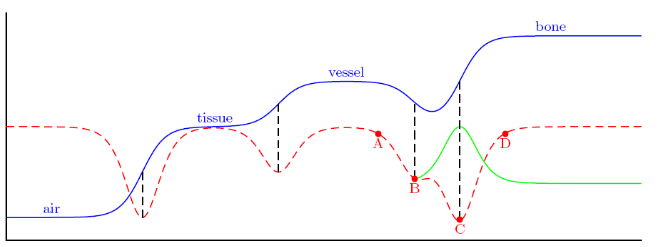
Sigmadetermines the width of the sigmoid function as can be seen in figure 6. When you look at figure 6, you can see it is important to keep it relatively small. The value is given in pixel units. Using the pixelspacing in the image, this will be converted to mm.Scalevaluedetermines the heigth of the sigmoid. I assessed this value by looking at the order of the mean value of the feature image. In my case it was 0.01. If you would choose this to big, you will also cause a shift of point B- The option
computescalevaluefrominputis a boolean (0,1). When enabled,vmtkimagefeaturecorrectioncomputes the mean value from the featureimage and uses this value to set the height of the sigmoid function instead of the value given to the option scalevalue.
 |
|
| Figure 6: Problem situation |
vmtkimagefeaturecorrection -ifile bone_feature_500.vti -levelsetsfile bone_air_lvlset.vti
-scalefrominput 0 -ofile sigmoid_feature.vti
 |
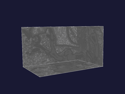 |
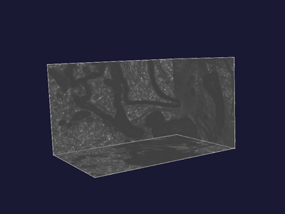
| Figure 7: Original feature image | Figure 8: Altered feature image |
Figure 7 shows the original feature image, figure 8 shows the altered one. In the latter figure you can see that some areas are brighter compared to figure 7. This is caused by the application of the sigmoid function
I recommend however to use a small standard deviation (for example one pixel) because then you will be able to use the curvature option more efficiently. If you will use a higher standard deviation , the curvature option has less freedom when creating the actual levelset. This is because they both erode the levelset a bit in order to create a better shape. The curvature is also capable of smoothing the surface of the aneurysm, which the sigmoid cannot.
Short explanation of the problem.
When looking at figure 6, the intensities of the different tissues are displayed by the blue line. The red dotted line represents the negative absolute derivative (for a more detailed explanation i refer to the PhD thesis of Luca Antiga). Normally when the bone is away from the aneurysm, a deformable model that would start at point A would evolve to point B. However, when bone is close, it will evolve to point C because this is the local minimum and not point B. A deformable model for bone starting at point D will always evolve to point C. If you look at the figure closely, you can see that the same can happen when air will come too close. The great difference in intensities between vessel and bone/air, cause the problem. The correction that is applied by the sigmoid function is the green line, which will cause the local minimum to shift to point B again.
Constructing the Aneurysm
Now the actual model of the aneurysm will be constructed.
vmtklevelsetsegmentation -ifile image_volume_voi.vti -featureimagefile sigmoid_feature.vti -ofile aneurysm_model.vti
To see the difference with the levelset without using the sigmoid function, exclude the -featureimagefile option from the previous command and make the model with the same protocol. Additionally you could create an initial levelset to compare the segmentation of the sac alone. (see next section)
I started at the aneurysm, because this was the most important reason why the sigmoid was introduced.
Aneurysm -> fast marching -> thresholds 250 - 500 -> 500 iterations
Place one source seed at the center of the aneurysm and one target seed at the border. After running the iteration step, you get a good impression of what your aneurysm will look like. The sharp edges can be removed by increasing the curvature option. High values for curvature will cause the surface to collapse, so increase the curvature in small steps.
My final values: 500 0 0.2 1.0
Vessels -> colliding fronts -> thresholds 250 - 500 -> 500 iterations
When the thresholds fail to make an initialization, the thresholds are adjusted until an initialization can be made. I kept the curvature at 0.0 (only at MCA, ACA and arteries originating from aneurysm)
Remove levelset region
If you want to remove a region afterwards because you are not satisfied with it, you can use vmtkimagevoipainter
vmtkrenderer --pipe vmtkmarchingcubes -ifile aneurysm_model.vti -l 0.0 --pipe vmtksurfaceviewer -i @.o --pipe vmtkimagevoipainter -ifile aneurysm_model.vti -paintvalue 10 -ofile aneurysm_model2.vti
The paintvalue has to be greater then the maximum value in the levelset. You could look this up by using vmtkimageviewer on the segmentation file. A value of 10 should be enough. vmtkimagevoipainter works in a similar fashion as vmtkimagevoiselector. Once you apply the painting, the image will get darker because there is a shift in the color scale due to the new value you have entered.
After painting, you can continue again with the levelsetsegmentation using
vmtklevelsetsegmentation -ifile image_volume_voi.vti -featureimagefile sigmoid_feature.vti -levelsetsfile aneurysm_model2.vti -ofile aneurysm_model.vti
Constructing the Internal Carotid
The first thing to do is to create an initial levelset of the internal carotid.
vmtkimageinitialization -ifile image_volume_voi.vti -olevelsetsfile intcarotid_initial.vti
Now you will have to construct the whole internal carotid. First it is wise to choose a small interval of thresholds in order to segment the carotid only and avoid the neighboring tissue. Second you should do the segmentation in small steps. This is also done to avoid the inclusion of neighboring tissue. In the end it is still possible that you have some extra tissue in your initialization, but try to keep this to a minimum. For the internal carotid artery I took 300 – 450 as a default value for the thresholds.
As you may have noticed, vmtkimageinitialization is also incorporated in vmtklevelsetsegmentation. I chose here to do it separately, but you could do the initialization and continue immediately with the segmentation.
Once you have created the initial levelset, you can make the actual model of the internal carotid.
vmtklevelsetsegmentation -ifile image_volume_voi.vti -featureimagefile image_volume_voi_sigmoid_feature.vti -initiallevelsetsfile intcarotid_initial -ofile intcarotid_model.vti
Notice that the option -initiallevelsetsfile is included now. This causes vmtklevelsetsegmentation to skip the initialization phase and it continues immediately to input for the numberofiterations, propagationscaling, curvaturescaling, advectionscaling.
My endvalues here were 500, 0, 0.2, 1.0
Why initial levelset
Initially I created a model of the internal carotid in the same way as described in the aneurysm section. However, this sometimes gave complications and took a long time. Afterwards I tried to make a model with an initial levelset which gave a result almost as good as the previous method, only taking two steps.
Creating the mesh
When you have made a model of the aneurysm and/or the internal carotid, you can proceed to make a mesh from the model. In this part I will use the aneurysm model in the code, but you can easily apply the same to the internal carotid.
The first step is to create a surface from the levelset.
vmtkmarchingcubes -ifile aneurysm_model.vti -ofile aneurysm_model.vtp
Then the surface will be smoothed
vmtksurfacesmoothing -ifile aneurysm_model.vtp -passband 0.1 -iterations 30 -ofile aneurysm_model_sm.vtp
In the rare occasion that in some regions on the surface strange peaks will appear, you can also use vmtksurfaceremeshing.
vmtksurfacereader -ifile aneurysm_model.vtp --pipe vmtkcenterlines --pipe vmtkdistancetocenterlines --pipe vmtksurfaceremeshing -elementsizemode areaarray -targetareaarray DistanceToCenterlines -targetareafactor 0.1 -maxarea 0.1 -ofile aneurysm_model_rmsh.vtp
Clip the surface with vmtksurfaceclipper (There are also other options to clip the surface, see From 3D surfaces to CFD meshes ).
vmtksurfaceclipper -ifile aneurysm_model_sm.vtp -ofile aneurysm_model_sm_cl.vtp
The next step is increasing the number of surface triangles. This is optional but I used this step every time I made the mesh. The used method is loop .
vmtksurfacesubdivision -ifile aneurysm_model_sm_cl.vtp -method loop -ofile aneurysm_model_sm_cl_sb.vtp
Then flowextensions will be added to the model.
vmtksurfacereader -ifile aneurysm_model_sm_cl_sb.vtp --pipe vmtkcenterlines -seedselector openprofiles -endpoints 1 --pipe vmtkflowextensions -adaptivelength@ 1-extensionratio 5 -normalestimationratio@ 1 --pipe vmtkflowextensions -extentionratio 8 --pipe vmtksurfacewriter -ofile aneurysm_model_sm_cl_sb_ex.vtp
The extensionratio 5 is used for the inlet, the extensionratio 8 is used for the left outlet, the extensionratio 16 is used for the right. This ratio determines the length of the extension. Because the inlet I created with clipping is usually pretty long, this ratio is smaller.
Creating mesh with vmtkmeshgenerator
There is a slight difference in steps you have to take when using vmtkmeshgenerator instead of NetGen. In this section, the use of vmtkmeshgenerator will be discussed.
vmtkdistancetocenterlines computes the distance between every node and the centerline.
 vmtksurfacereader -ifile aneurysm_model_sm_cl_sb_ex.vtp --pipe vmtkcenterlines -seedselector openprofiles --pipe vmtkdistancetocenterlines -ofile aneurysm_model_sm_clip_sb_ex_ds.vtp

 vmtkmeshgenerator -ifile aneurysm_model_sm_clip_sb_exds.vtp -elementsizemode areaarray -targetedgelengtharray DistanceToCenterlines -targetedgelengthfactor 0.25 -maxedgelength 0.25 -boundarylayer 1 -ofile aneurysm_model_mesh.vtu
The following code transforms the elements from linear to quadratic elements.
vmtklineartoquadratic -ifile aneurysm_model_mesh.vtu -ofile aneurysm_model_meshq.vtu
With vmtkboundaryreferencesystems the radius, center and normal of the flowextension opening can be determined. It uses surfacefiles, therefore I used the inputfile you see below. Also scaling is applied because the mesh will also be scaled from mm to cm.
vmtksurfacescaling -ifile aneurysm_model_sm_clip_sb_ex.vtp -scale 0.1 --pipe vmtkboundaryreferencesystems -ofile aneurysm_model_mesq_ref_sc.vtp
This step scales the mesh from mm to cm
vmtkmeshscaling -ifile aneurysm_model_meshq.vtu -scale 0.1 -ofile aneurysm_model_meshq_sc.vtu
Finally the mesh is written to libmesh format. This is also dependant on the solver you are using. Here I used a solver that is currently in development. Generating an inputfile for a CFD solver.
vmtkmeshwriter -ifile aneurysm_model_meshq_sc.vtu -entityidsarray CellEntityIds -ofile aneurysm_model_meshq_sc.xda
Creating mesh with NetGen
In this section, the use of creating a mesh with NetGen will be discussed
The first thing to do is to cap the flowextensions so you have a model with closed extensions. Afterwards the file will be written to a .stl file which can be opened with NetGen
vmtksurfacecapper -ifile aneurysm_model_sm_cl_sb_ex.vtp -ofile aneurysm_model_sm_cl_sb_ex_cp.vtp -interactive 0 --pipe vmtksurfacewriter -ofile aneurysm_model.stl
The option -interactive is set to 0, so vmtksurfacecapper will automatically cap all open extensions. If you want to do manually, set the option to 1.
NetGen is an open source mesh generation tool. Download NetGen or instal from the ubuntu repository. For a more detailed explanation see Meshing with NetGen.
Remove spurious edges with STL doctor
Mesh Options --> mesh granularity on very fine and second order element. Then set STL - chart distance to for example 4.0 to make the mesh coarser. Mesh --> Edit boundary conditions: assign the correct boundary properties to the inlet, outlets and wall Change the bc properties in the following way.
1 --> 2
2 --> 3
3 --> 4
4 --> 5
`export mesh --> filename.neu`
With meshscaling you have to convert the model from millimeters to centimeters.
vmtkmeshscaling -ifile filename.neu -scale 0.1 -ofile filename.vtu
After this step you are ready to generate the input for your solver. This greatly depends on the solver you are using. Generating an inputfile for a CFD solver.
If you have any questions, feel free to contact me at R.P.M.Jansen@student.tue.nl